CI stucco could affect methods used in future building codes. By Christopher K. Little
The Evolution of Continuous Insulation–Stucco Systems
xxxxx. xxx
xxxxx
xxxxxxxxx
xxxxxxxxxxxxxxx By xxxxxxxx
h2 - xxxx
h3 - xxxx
H1 headline
Portland-cement plaster, aka stucco, continues to have a preferred position in the cladding marketplace for U.S. residential and commercial building. Recent findings from Fredonia Consulting show that stucco is applied to about 20 percent of the exterior cladding market, up 5 percent over the past three years. This demonstrates the public’s desire to have their buildings and homes constructed with stucco.
However, lath and plaster have seen a decline in certain markets where stucco or thin-veneer stone walls were poorly assembled, taking in water and then not being able to dry out. These issues are more prevalent in the eastern U.S. and along the Pacific Coast, where 20-plus inches of rainfall annually is common.

Damage to stucco cladding due to moisture intrusion.
In fact, a large portion of the country is now required by code to provide a capillary break behind these “absorptive claddings” to facilitate both drainage and drying. These regulations encompass Climate Zones 1, 2 and 3, which includes most of the Southeastern U.S.; the “Marine” zone along the west coast; and the “Moist” zone, which includes areas east of Colorado. Section 703.7.3.2 of both the International Building Code and International Residential Code—water-resistive barrier requirements behind where stucco is applied to wood-based sheathings (plywood and OSB)—are divided into separate sections for dry and moist climate zones, with a 3/16-inch air space or material with high drainage efficiency required in moist climate zones. The building industry is recognizing the enhanced performance this 3/16-inch ventilated space provides, and specifications for various furring and rainscreen systems are growing in specifications and use.
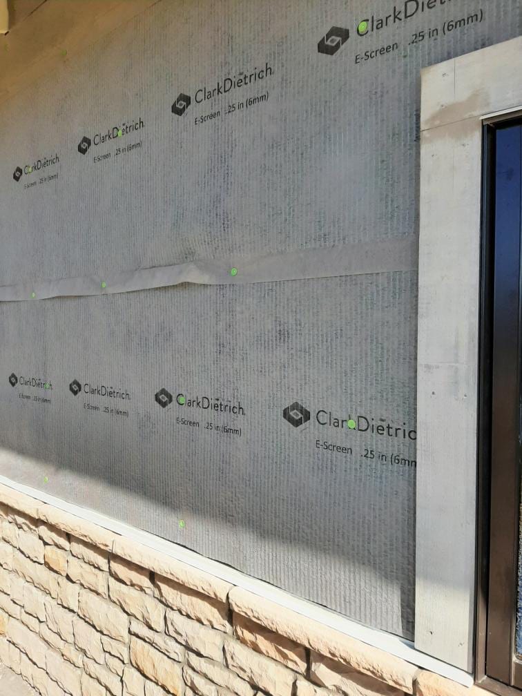
6-millimeter drainage mat over sheathing for stucco and/or stone.
In 2009, the International Energy Code increased energy efficiency in 2x6 steel-framed walls in commercial construction. Normally, project teams would compensate with more batt insulation inside the wall cavity, but that approach does not consider the thermal bridging produced by the metal or wood framing. When using a correction factor, the actual thermal value is lower than design value. Therefore, the advent of continuous insulation on walls, or the adding of board insulation outside the sheathing, became the new standard CI design in the U.S., though builders in the western U.S. had been constructing homes and buildings this way earlier than 2009. Yet, with stucco applied to continuous insulation, the challenge of lath attachment started to evolve. Some of the approaches now used are described in this article.
Fasteners Used for CI Stucco
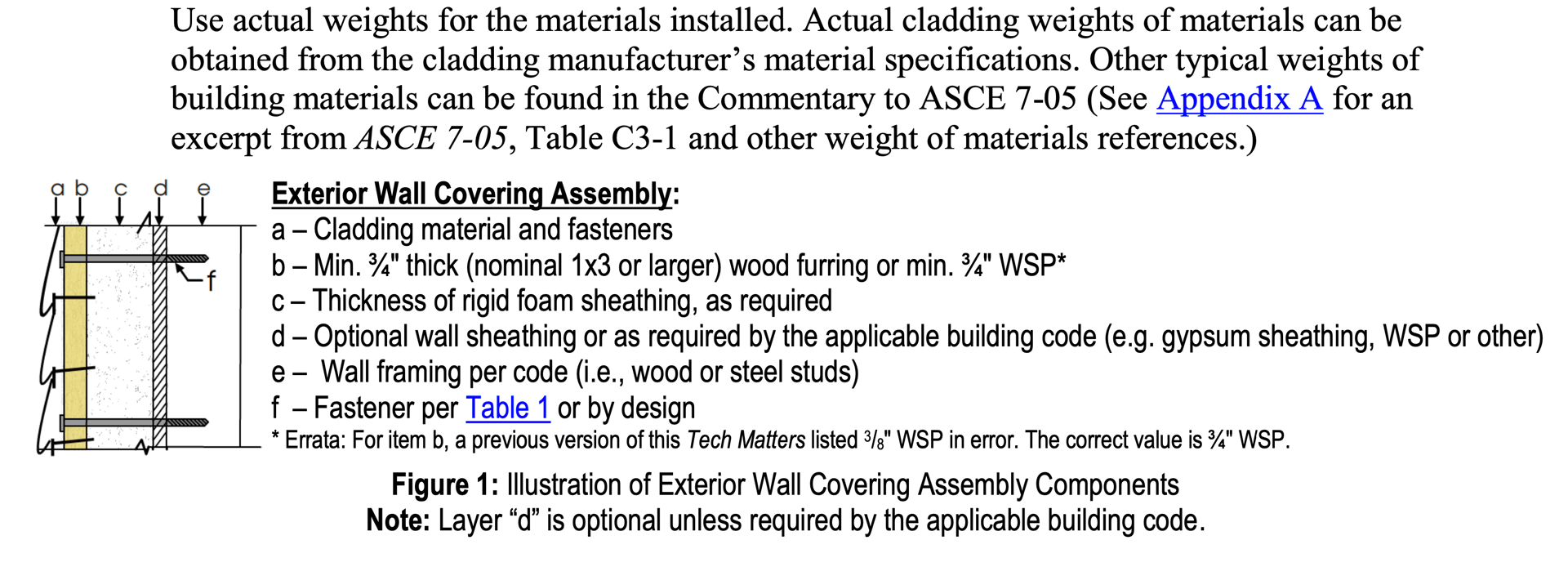
For a stucco cladding on continuous insulation, one must consider the repercussions of mechanically fastening the lath through the 1 to 4 inches of insulation and its associated deflection. Recognizing that 3/4-inch of cement-plaster weighs 10.3 pounds per square foot, that screw deflection means selecting the appropriate fastener to manage the load. Fortunately, we have guidance from the IRC/IBC on this now, in Chapter 26–Foam Plastics. Multiple tables found there, beginning with Table 2603.12.1—“Fastening Requirements Over Foam Plastic Sheathing to Support Cladding Weight for Steel Framing”—consider the deflection of the fastener based on length and load at the end of the fastener (see the illustration).
Other factors to consider include thermal transmission through the screws, which is not defined. Yet, innovative materials like non-metallic washers or plastic-sleeved screws demonstrate limiting heat flow. Furthermore, fasteners running through the insulation system can provide a conduit for incidental moisture and must be addressed via re-direction/flashing or sealants and coatings. These solutions will continue to develop as demand for CI-stucco systems remains.
Excerpts from the Foam Sheathing Coalition Report: https://www.wccinfo.org/Files/library%20claddding%20attachments.pdf
Another CI-Lath Attachment
Another common structural design for CI-stucco systems is the use of Z-furring. Z-furring is installed to allow board insulation to be sandwiched in-between the furring to reduce thermal bridging and serve as a substrate for the outboard sheathing or framing to attach the metal lath. In this design, the insulation is fitted in-between the Z-furrings to achieve CI stucco, where the lath fastening approach is more in-line with the traditional ASTM C-1063.
For example, if the Z-furring is fastened through an exterior sheathing into the wall framing, spaced at 16 inches on-center and running vertically in line with the walls, the metal lath—sheets or rolls—would fasten perpendicular to the Z-furring with the same vertical spacing as found in the ASTM standards (7 inches o/c) down the Z-furrings. The lath’s weight selection would be determined by the “allowable span” table found in Table 1 of ASTMC-1063-23 for welded, woven or expanded metal laths. If the Z-furring is attached horizontal to the wall, i.e., perpendicular to the vertical framing members, then the lath direction changes to maintain the ASTM C-1063 for attachment—“Lath shall be installed with the long dimension at right angles to the framing members…” (Section 7.3.1.3). Currently, I am aware of only one lath product that has an approval to install lath for vertical installation on horizontal framing members (see the photo below).

Section detail for Z-furring installed under stucco.

Fiberglass Z-girts (green) installed horizontally, with rainscreen (blue) and wire lath installed vertically.
Need to update flourish table
Drainage Planes with Lath and Plaster
Drainage planes are coming, and they make sense with the right systems. These can be furring strips, drainage mats or drainable housewrap over the substrate. However, when metal lath is installed over them, the importance of full 1/4-inch furring on the lath—be it dimples or v-grooves in the sheet or bends in the wire—this feature must be present.
In-house visual testing by my employer determined that non-furred laths over any drainage mat or wrap does not allow adequate space for plaster embedment into the lath. Furthermore, even listed “self-furred” laths, where the embossed furring becomes compromised, can make scratch-coat embedment difficult to achieve. However, that same visual testing showed welded-wire lath with uniform self-furring of 1/4-inch enhanced the ability to embed the scratch-coat on entangled mesh drainage mats. The need to embed the metal lath does not go away when a drainage plane is integrated into the CI-stucco wall.

xxxxxxxxxxxx


Fiberglass Z-girts (green) installed horizontally, with rainscreen (blue) and wire lath installed vertically.
Traditional diamond mesh lath (left) and welded-wire lath (right) installed with a drainage mat.
In conclusion, the use of CI-stucco claddings will continue to gain preference in the marketplace. As product innovation emerges, I believe we will see refinement in the way we design and install these CI systems and, ultimately, see some of those methods prescriptive in the codes. By doing so, inclusion into codes and standards make CI stucco a viable cladding in the next generation.
References
- xxxxxxxxxxx
- xxxxxxxxxxx
Images courtesy of ClarkDietrich.
Chris K. Little is senior product manager at ClarkDietrich. He has nearly 30 years of experience in new product development and management and plays an integral role in helping shape industry standards for lathing, plastering and installation of masonry and stone. He can be reached at c.k.little@clarkdietrich.com.